Product Design
Raspberry PI Scanner V2
Second version of the 3D Scanner build. Bellow you can find a free to use build guide together with the STL files and schematics, as well as the python code.
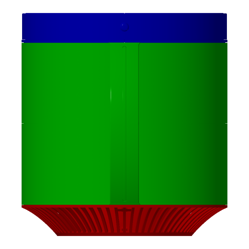
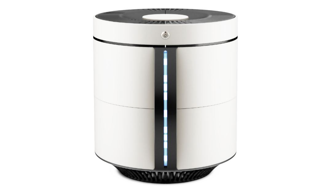
This is what the assembled scanner looks like.
Note before you start: This is a complex build. It requires a fair amount of 3D printing knowledge, knowing how to connect electric and electronic components, some soldering skills, and a lot of patience and skillfulness. I’m giving the plans for free and I cannot bear any responsibilities for any loses or injuries, as well as no guarantee that it will work out for you.
List of things you need:
White PLA – 1kg
Black PLA – 1kg
Transparent PLA – 100gr
3-5 Raspberry Pi Zero (depending on your build)
3-5 Raspberry Pi Camera (same number as R Pi’s)
LED Light ring 25cm diameter and 16cm (optional)
Power supply 56x84mm 220-12V 2-5A
12V-5V Step down
NEMA 17 Stepper motor 42x42x57mm
L298N Controler for Stepper
683ZZ 3x7x3mm Ball Bearings
Some tools, hot glue gun
Some M3 Screws and bolts
M3 Brass Hex Column Standoff Support Spacers 6mm and 10mm long
Building the base
Step 1
As shown in previous section, the device consist of 3 main sections: base, body and cover. Base consist of the electronics and moving parts, body is mainly to support the overall device, and the removable cover consist of lighting assembly and the power switch.
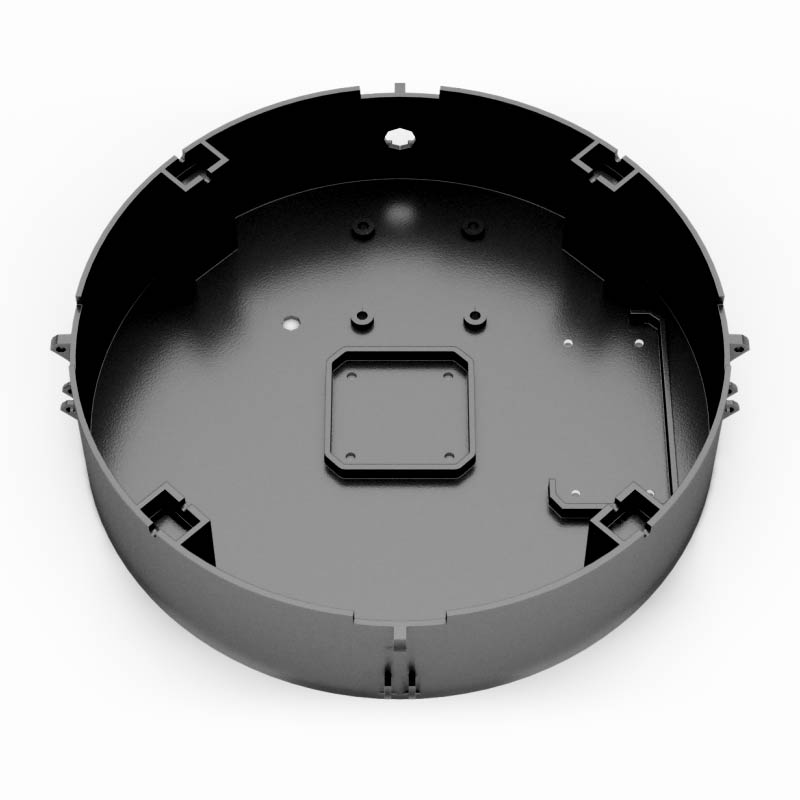
Start with 01_Base_main_box.stl
Everything goes in here, electronics, power supply, RPis.
Step 2
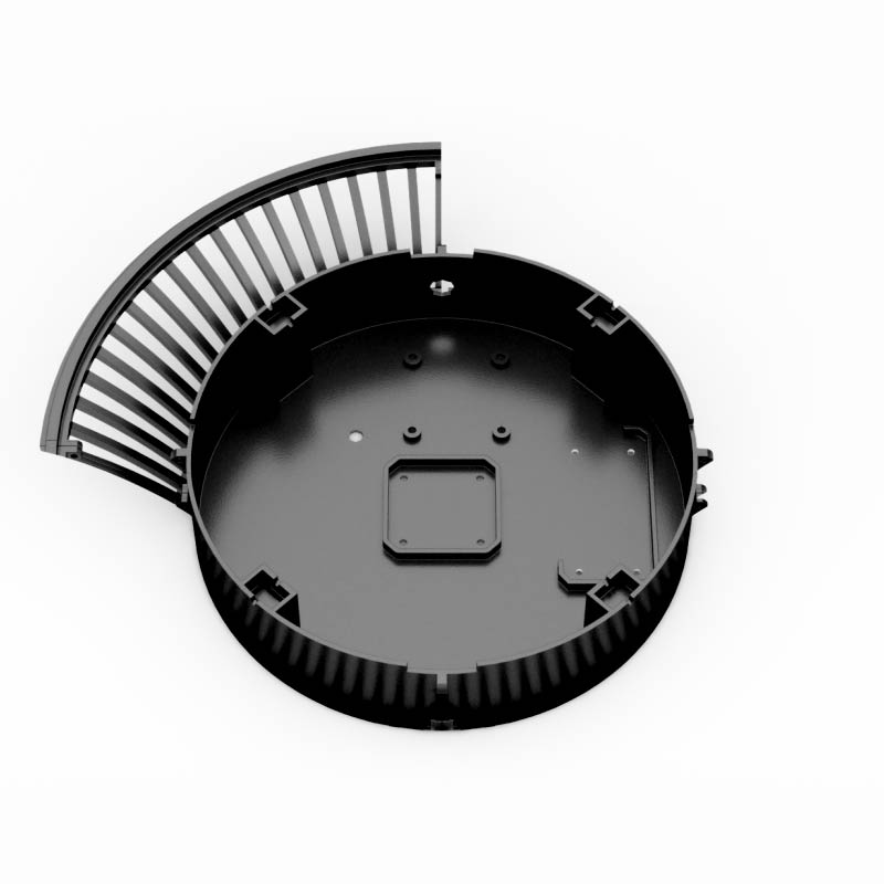
Take 02_Base_grill_x4.stl and arrange them around the base.
Step 3.
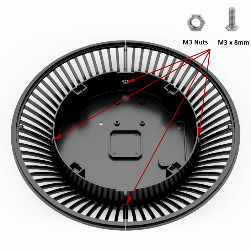
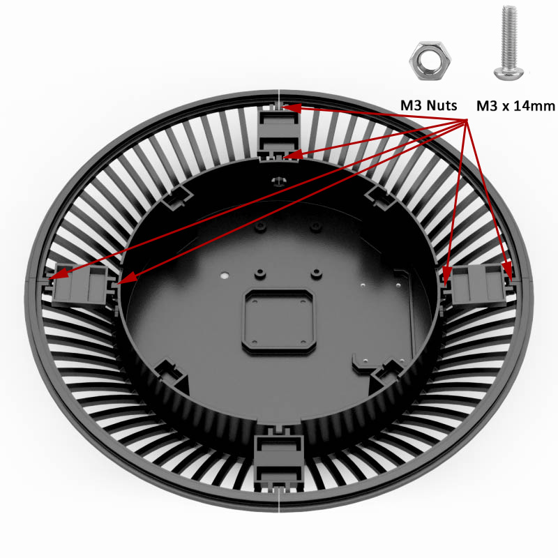
Align all 4 grills and secure the bottom parts with M3 screws.
Step 4.
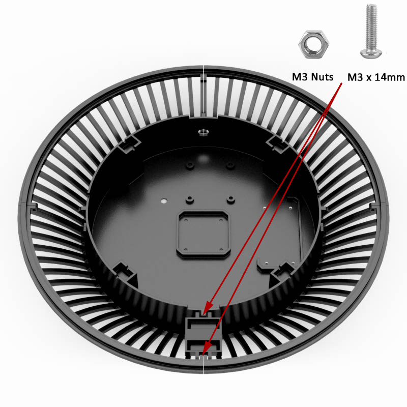
Place the 03_Base_grill_connector_wide.stl and secure it with screws on both sides.
Step 5.
Repeat the same on other 3 sides. The assembly should feel solid once you are done. Beware: do not tighten the screws too much, as PLA can be brittle on thin parts.
Note: 03_Base_grill_connector_wide.stl part has some space to place the wires and flat cables underneath. It’s made that way to make wiring easier and neater.
Step 6
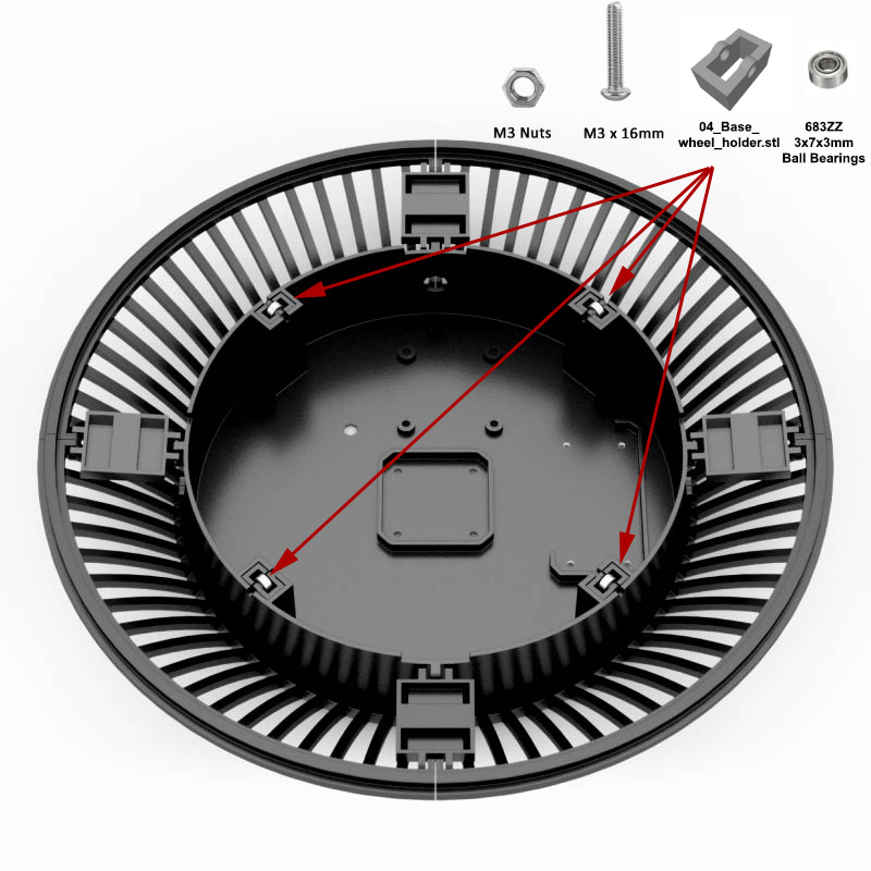
Take 04_Base_wheel_holder.stl and 683ZZ ball bearing and place them on 4 sides and use the M3 screw and nut to secure them in place. Make sure the ball bearings are rotating freely as the disc will be rotating on them.
Step 7
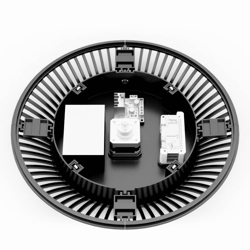
Place the electronics parts here as pictured. You will need to add step down 12V to 5V adapter to power up R Pi’s. Bear in mind they draw fair amount of current so I would recommend 8A one, or couple of separate ones. Because I don’t know the size of the one you might use, there is no predefined space in the base for it, but you can always hot glue them in place.
Note: It is a good idea to have everything connected and working before assembling the device to make sure you do not have to remove the parts later on. Refer to Fritzing Schematics file in the download section on how to connect and program parts.
Step 8
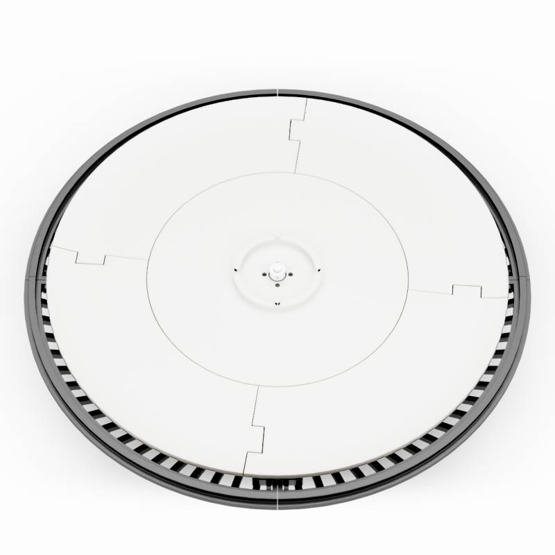
Hot glue four 05_Base_plate_x4.stl parts together like in the image. There is no need to place them on the base just yet, wait for the completed plate.

Step 9
Hot glue 06_Base_plate_central.stl and use 4 M3 screws to screw the 5mm flange to it.
Place the disc onto the motor and make sure it rotates nicely. Secure the flange to the stepper.
Note: I tried to make this as simple as possible because you might need to remove the disc often until everything works.
Step 10
Place the 07_Base_plate_cap.stl on top of the platform. It should fit snugly on top.
Note: You can modify this cap to your needs to secure the objects being scanned – this cap makes sure they don’t fall over.
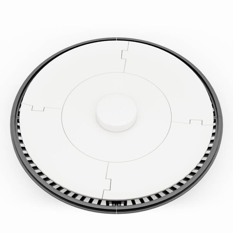
Step 11
Onto the body building. Place the four 08_Body_wall_lower_x4.stl around the base. These parts have holes in it should you wish to place LED light wires.
Note: You might want to hot glue these to each other to make them more stable.
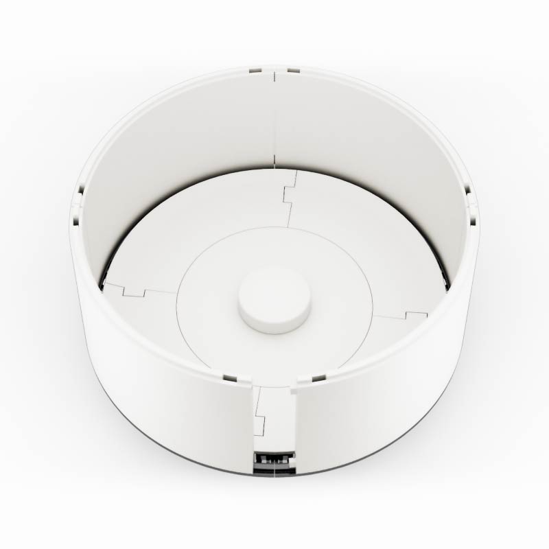
Step 12
Continue with the four 09_Body_wall_upper_x4.stl to make the body walls.
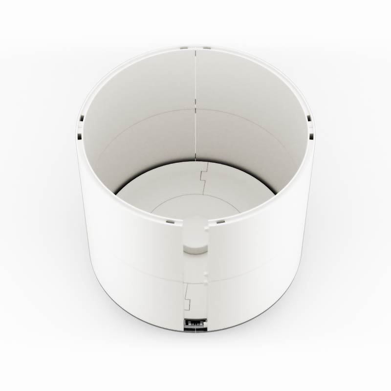
Step 13
Place the 11_Body_front_cover_trans.stl into the 10_body_front_cover.stl. Again you might want to glue these to each other if they don’t fit exactly.
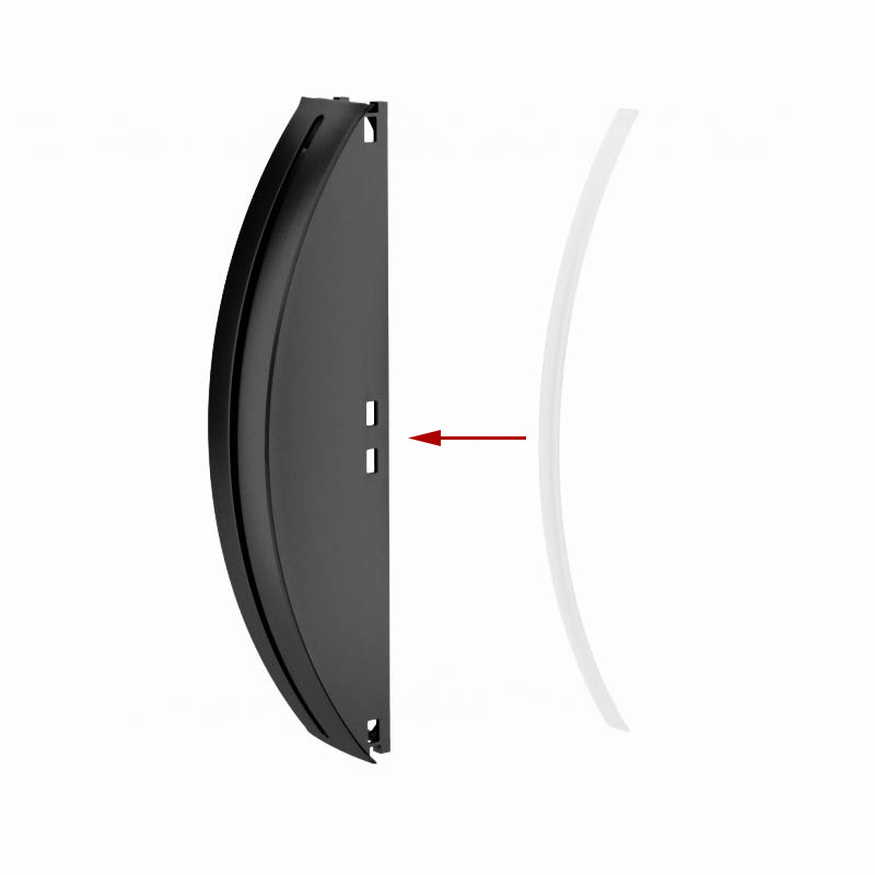
Step 14
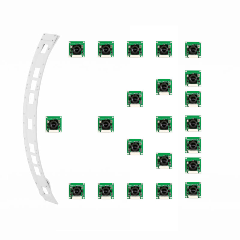
Place the Raspberry Pi cameras into 12_Body_body_cam_holder.stl. Bear in mind there are two versions of this file, version B has the topmost and the bottom cameras tilted a bit to make better angles. I recommend version B.
Note: Place the cameras depending on your configuration. You can place up to 7 cameras onto the holder. Be careful of the flat cables, they break easily.
Step 15
Place the holder with cameras into the front cover.

Step 16
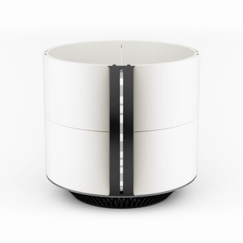
Finally, place the front cover and connect the walls to it. When together, the whole body part should move together. This concludes the body part.
Note: Now comes the tricky part. You need to connect the cameras to the Raspberry Pi’s. Camera connectors on Pi Zeros are very touchy and I managed to break all four of them. Be really really careful with them as this is a very frustrating part. I used cable extenders and simply hot glued the connections on the Zeros. Also, you need to make sure cameras are in focus with the subject and, again, this is a weak point of these cameras.
Step 17
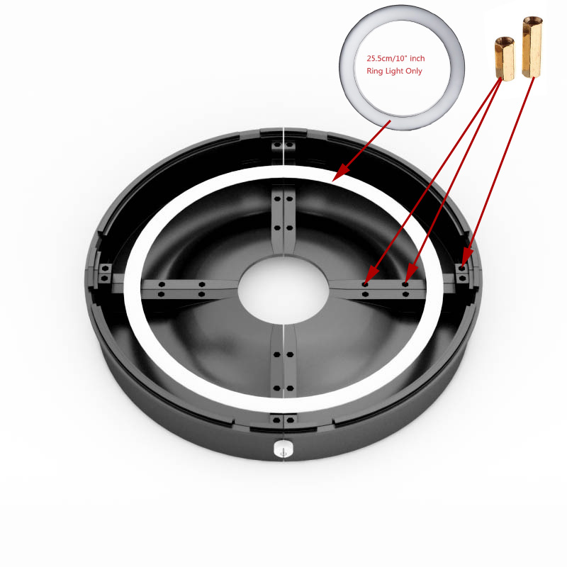
Onto the top cover part. You’ll need two 13_Cap_back_x2.stl parts as well as 14_Cap_front_right.stl and 15_Cap_front_left.stl. Place them like in the picture (front parts have a hole for the power switch. If you are not using it, just use two more back parts). Place the LED ring on top, place the switch in the front. Finally, place the hex standoffs in their holes.
Step 18
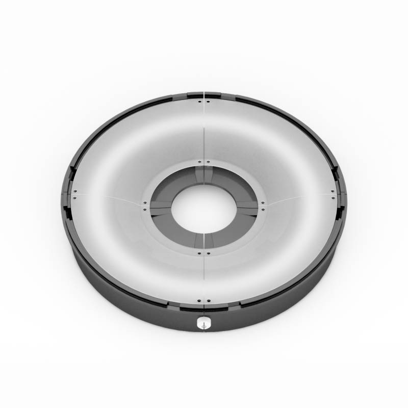
This step is optional depending on your LED lights. You need to print out 16_Cap_light_diffuser_x4.stl in transparent PLA and place it on top of the light to get more even lighting.
Step 19
Place 17_Cap_Handle_Bottom.stl over the diffusers or just on top if you are not using them. Make sure wires are placed outside in the holes provided.
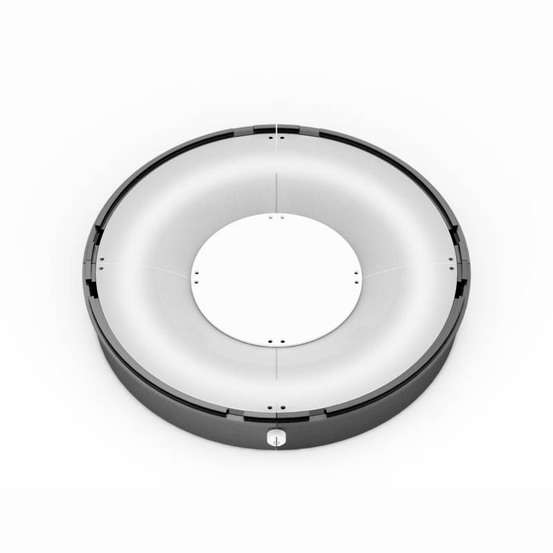
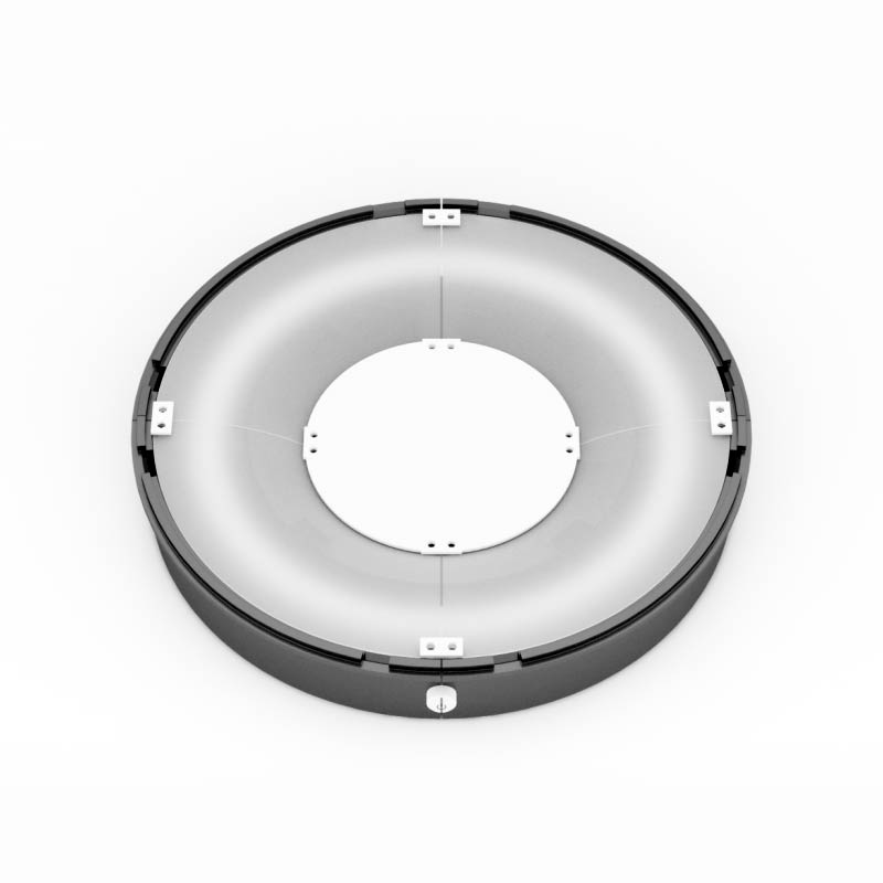
Step 20
Place eight 18_Cap_Connectors_x8.stl over the wholes and tighten everything with M3 screws. Length of the screw will vary whether you used diffusers or not.
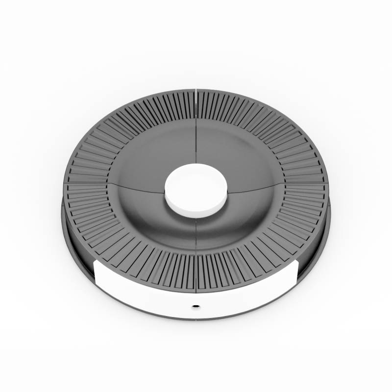
Step 21
Turn the cover around and place 19_Cap_handle_top.stl on top, it should fit nicely with the bottom part. Place the 20_Cap_cover_front.stl on the front and push the switch in. If you are not using switch just use the another 21_Cap_cover_sides_x3.stl (print four of them)
Note: 20_Cap_cover_front.stl and 21_Cap_cover_sides_x3.stl are there to make it look nicer. You can do without them, but if we got this far, we might as well use it.
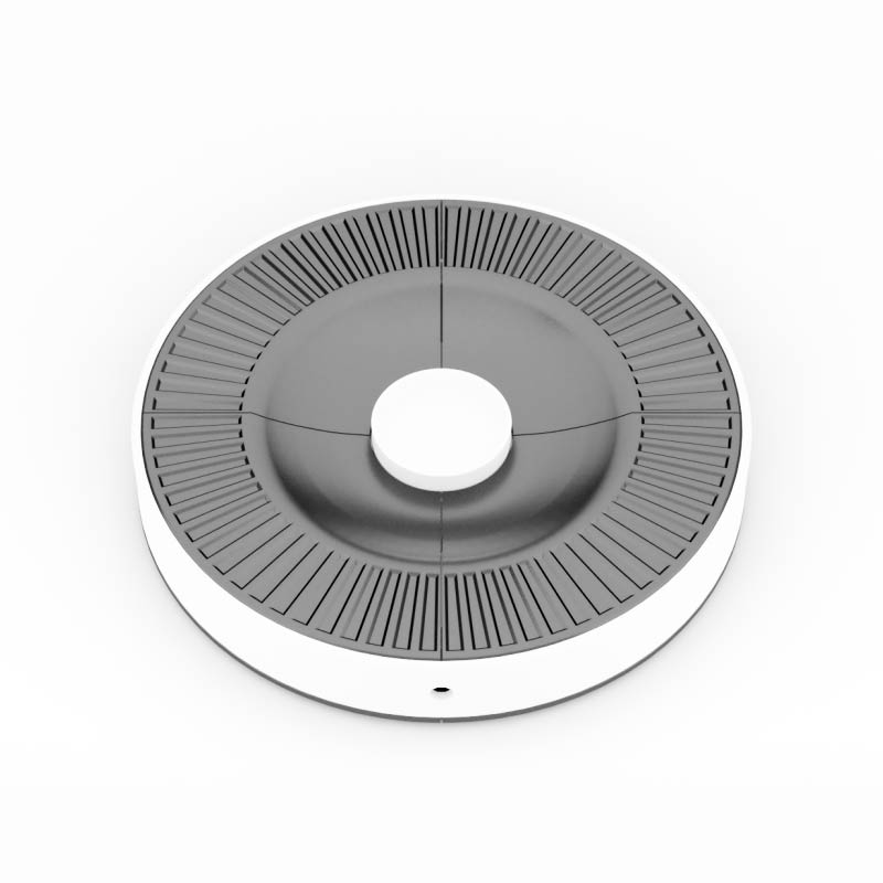
Step 22
Place 21_Cap_cover_sides_x3.stl around the cover. Hot glue them in place. I recommend white or transparent one.
DONE!
Well not quite. You still need to connect the switch and LED’s and test it all. Also, at this point, there is no user interface so you will need to use command prompt and python commands to actually make it work, but hopefully that will be fixed in the near future.
Download section
Here you can get the STL files. Fritizing schematics are coming really soon. Files are provided as is, however if you have any questions please let me know. Click on the image to download.
Note:
There was a tiny glitch regarding the 02_Base_grill_x4.stl file, ZIP archive containing the updated file is linked now, so if you have any issues printing that one please get the new archive.
If you wish to donate crypto you can use one of the currencies underneath
BTC
13FTb6vns9ggPVJU3zDvvcpUbRFfvuHgeh
BCH
qqv2c3gp2y54q3hu5ksm8uzq8wqa6vm2r5ud8ks5fl
ETH
0x0b1e6329667ff3ea374bdaba4c6dd44f5d37c4b5
LTC
LMUQrKEcwovjeHzdE8DECdtEodcwz1RPWZ
XLM
GAKYYLXBQZRNKGLMRKYGTME35LK2OLXY5DSZUXH36PZ4KHUVSREA7T45
XRP
rnWASZJ267RHaMyeqCrmYAq3DxLdp5YHcy
Need Help with the project?
Send your inquiry in the form bellow and I’ll be back to you as soon as possible.
Thanks!
